|
|
|
|
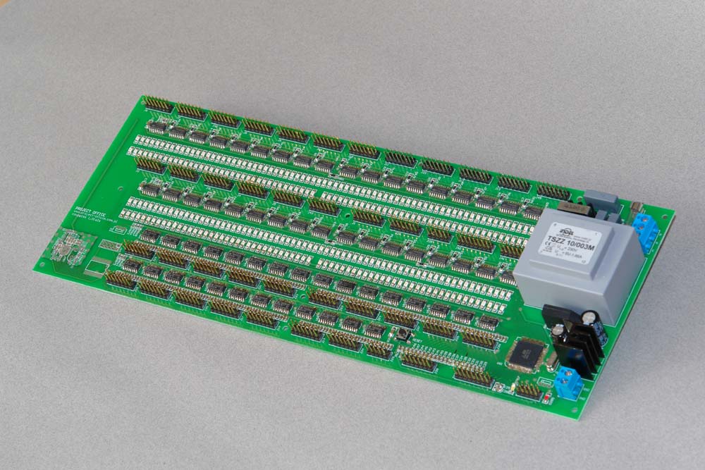
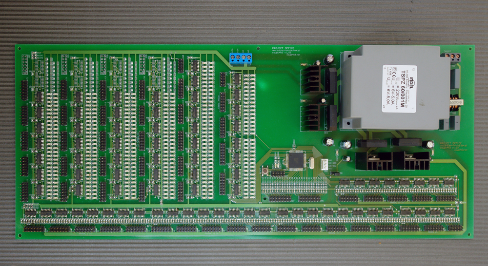
Couple board - technical data
- independent power supply or voltage rating: 5V
- supply current without external devices connected: 400 mA/600 mA (depending on the number of manuals)
- output voltage: TTL levels (or otherwise according to the order)
- input voltage: TTL levels (or otherwise according to the order)
- maximum output current: 5mA
- number of couples: 27 (or otherwise according to the order)
- separate signal outputs which indicate the connection activation (load - one LED or otherwise according to the order)
- connection activation input voltage: 12V/24V
- optically insulated activation inputs
- number of manual octaves:
- number of coupled octaves: 5 + super
- number of pedal octaves: 2 + c÷g (or otherwise according to the order)
- boards enable any couple also after being installed in the organ
- boards enable changing the programmed couples after being installed in the organ
- boards enable coupling additional stops that are not associated with any manual (according to the order)
- boards are suitable to work with photocells boards, tone relays and setzers or otherwise according to the order
- dimensions: 340 x 130 x 40mm (the given height takes into account elements on the bottom side of the board)
- parts height above the board: 35mm
|
|
|
Specification
Couple boards enable using stops of one manual while playing other manual or manuals/pedal. The standard board version offers 27 possible couples (or as specified in the order). We can switch on a couple by controlling one of the 27 optically insulated inputs. The optical insulation allows galvanic separation of electronic module supply voltages from supply voltages of executive units. This solution makes the electronic modules resistant to all kinds of disturbances that come through power supply wires and are caused by switching on inductive devices. This requires that the connections where we connect the photocells manual boards and the photocells pedal boards should have two pins with power supply for these boards.
Each manual and pedal octave is connected to the couple board with a separate 14-wire tape. The number of used wires depends on number of tones in the octave. Two of them are voltage supply wires for photocell boards. There is a separate connector on the couple board for each octave.
Apart from the stops associated with individual manuals, the device can manage other stops which are not associated to any manual (according to the order). This solution makes the couple board more universal, especially in case of repaired organs.
The couples are activated by the processor. Therefore they can be freely defined and changed (by the manufacturer) any time. The tone valve control outputs are also grouped in octaves. Each of them has a parallel LED which is turned on when we press a key on the keyboard or a coupled keyboard. These LEDs allow fast location of a fault in the photocells board as well in the couple board.
| |
| |
|
|
|
|